Using several Internet Providers : MultiHoming
Starter
When I presented my home personal network stack I talked about applying to several ISPs (Internet Service Provider).
This blog post is about how to do that technicaly in the router, and talk about several possible routing scenarios.
We'll mainly talk about IPV4 configuration, as today, sadly, IPV4 is still much more used than IPV6. I could also give some words on the IPV6 connections.
As usual, we'll cover together what I did, for my needs, but give some ideas for other needs and fields as well.
Also, commands and examples will use the RouterOS syntax, that you'll adapt to your routing OS.
Configuring or throwing away your CSP
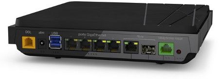
In France, we call them "boxes". Those awfull CSP your ISP gives you in the package when you apply to a commercial offer.
Those CSP are cheap hardwares, often buggy (sometimes security-holed), very limited, closed and not normalized (each vendor has its own concepts, its own UI, etc...)
Your ISP gives you such a box because it eases things from its own side : it knows what kind of hardware is plugged by the customer at the other side of the wire. Usually it embeds a modem and a very poor router.

Not all of them are crap, some CSPs are better than others but once more : if you turned to professional hardware, if you bought your own router from a known and serious brand, then you'll experience much much more power than with the CSP only. Also, if you go from ISP#1 to ISP#2, you keep your hardware and all your network configuration. There are many advantages to buy your own equipment and don't use the one provided by your ISP.
I started Internet access back in 1996-1998 era. At this epoch, CSP simply did not exist : you had to buy your own modem, and your own router. I still do that nowadays, why change ?
So, depending on your Internet access technology, you may be able to directly plug the "Internet wire" into your router, get your ISP connection details (technical ones, plus the credentials if available/needed) and plug-in/connect.
Depending on the access (PPOE, DHCP, etc...), you'll mount the right interface type on your router, and go.
Internet access at home, is just a small part of the global network management right ? An ISP makes use of regular worldwide known protocols, because it needs to interconnect with others, and it needs to be able to hire people that have been taught the common worldwide known protocols. There is no reason why your ISP would create from scratch its own way to connect you to the Internet. That's silly.
However, some (in France there are) fork a protocol, and add custom rules which are not RFC'ed. Here, you'll need a brain, TCPDump, and some port mirroring to toy and reproduce the exact frames so that the remote ISP equipment is fooled thinking it talks to its CSP.
In case you can't throw your CSP away, perhaps you can get it to bridge the connection ?
Whatever, chances are you'll end up with that :

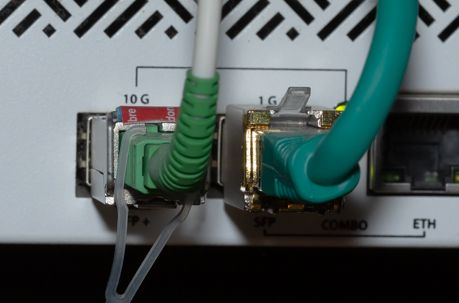
This picture is taken from my router. My ISP#1 is optical-fiber-to-the-home, so I plug-in the fiber directly into the SFP socket. This is the socket you can see on the left from the picture above.
Warning: If you don't know yet, SFP are the current way to universally connect things together but... There exists some incompatibilities, yes, that's weird. Read the documentation of your router, ask the company or read forums to know about compatibility.
Even if my applied bandwidth is 1Gbps down, I plugged it on the 10Gbps SFP+ port of my router, so that in case of a future bandwidth upgrade from my ISP, I should benefit from it directly.
Usually, the SFP itself is provided by the ISP, this was the case for me : my ISP#1, Orange, provided me with this SFP when I applied. Inside the SFP is written the VendorID, which will authenticate my socket against their hardware, thus I can't plug-in my own SFP, there is zero chances it could work (except if I overwrite its VendorID, I take that as a challenge and will experiment ^^).
Here are some details about the SFP that my router can read once plugged:
/interface ethernet> monitor sfp-wan-orange
                    name: sfp-wan-orange
                  status: link-ok
        auto-negotiation: disabled
                    rate: 1Gbps
             full-duplex: yes
         tx-flow-control: no
         rx-flow-control: no
      sfp-module-present: yes
             sfp-rx-loss: no
            sfp-tx-fault: no
                sfp-type: SFP-or-SFP+
      sfp-connector-type: SC
     sfp-link-length-9um: 20000m
         sfp-vendor-name: SERCOMM
  sfp-vendor-part-number: FGS202
     sfp-vendor-revision: 0001
       sfp-vendor-serial: ****************
  sfp-manufacturing-date: 17-12-25
          sfp-wavelength: 1310nm
         sfp-temperature: 44C
      sfp-supply-voltage: 3.3V
     sfp-tx-bias-current: 13mA
            sfp-tx-power: 1.9dBm
            sfp-rx-power: -20.262dBm
         eeprom-checksum: good
         *********************************
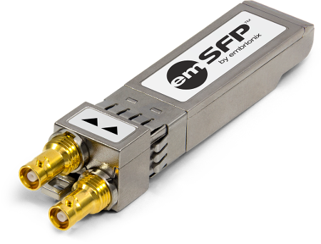
Should you know that there exists SFP to connect everything (mainly fiber light-transmission based), including ADSL/VDSL. This is a way to get rid of the ISP CSP :

Back to my router sockets, the rightmost one is a traditionnal RJ45 plug coming from a CSP I did put in bridge mode. I connected that RJ45 socket onto an SFP socket of mine, that way my Internet connexions are stacked on the left of the front router panel. On the right is the trunk to the switch (LACP, so 2 wires, the black ones). Then come an RS232 link to the power inverter. All other free plugs are free for different scenarios I could meet in the future.

That second ISP socket is totally transparent (L2 bridged) and let my router communicate through Layer 2, and get its IP address from the DHCP server of my ISP#2.
As this ISP#2 (which is SFR) uses DOCSIS, and as DOCSIS is an alien (understand by that the less common way to distribute Internet access), I haven't tried anything about it, certainly not this :

What you must not do, is build a double-NAT IPV4 stack. That goes the exact opposite of how IP stacks have been designed to work (true end-to-end connectivity, which IPV6 solves like a charm). So you have to plug-in directly to your router, or disable the router from your CSP (L2 bridge)
Getting your IP addresses from ISPs
Ok now you need to get your network details (IP address, network, gateway, other stuff) from your ISPs. Several scenarios here :
- Your ISP runs an old stack, and still uses PPPOE. PPPOE is an old way of connecting to the Internet. It has some drawbacks (MTU mainly), and as networks are slowly evolving from DSL to Fiber based, usually ISP takes this step to get rid of old PPPOE technology. With PPPOE come credentials from your ISP.
- Your ISP has evolved to a more recent stack, and provides access using DHCP (which still could require some credentials to authenticate).
Get some informations before applying. If you think you won't be able to make it, don't apply. Also, don't ask those sales about technical details, they won't be able to answer. Get some technical informations from the ISP technicians directly, should you reach them through forums on the Web.
For me, my two ISPs presented here always use DHCP to provide network information to their customers, but take care : they may use VLANs. ISP#1 for example, provides 3 VLANs, and Internet access VLAN is VLAN832.
You can spot that by sniffing the CSP traffic, that's not hard to do as soon as you know the protocols, and what to look for.
I sometimes apply to three ISPs, to test a third one, and then leave. I however always have two separate ISP applications at minimum.
Sometimes they provide you with a fixed IP address. That's mandatory for IPV6, but not for IPV4 (which is perfectly logical), so it may happen than sometimes you have to enter you IP address into your router by hand, instead of getting it provided by DHCP or PPP.
Routing all together
Connected routes
Now that we got two connections from your ISP#1 and ISP#2, let's try to route that.
We should not add the default route dynamically into the routing table when receiving the gateway infos from DHCP. Doing so, the default route will be dynamically attached to an interface, and we won't be able to play with it. We should only keep the two connected routes, and add the default gateway routes manually (static routes).
The connected routes are dynamic, which is obvious. We can see them here :
> /ip route print where connect
Flags: A - active, D - dynamic, C - connect

        DST-ADDRESS        PREF-SRC        GATEWAY            DISTANCE
 1 ADC  78.119.152.0/23    78.119.153.36   sfp-wan-sfr               0
 2 ADC  82.124.184.0/21    82.124.191.22   vlan832-orange-...        0
A connected route is a route to a connected interface. Connected routes are usually the last ones resolved by the router in the routing decision.
Perhaps you'll need to go back to your router manual about how routes work. Here it is for Mikrotik.
So from connected routes, I learn that if my router wants to reach the 78.119.152.0/23 network, it'll then need to send the packet on sfp-wan-sfr interface, using 78.119.153.36 as src address. This is effectively the address I got on this interface (from DHCP). Look :
> /ip address print
  Flags: D - dynamic
         address           network        interface
  7 D 78.119.153.36/23   78.119.152.0    sfp-wan-sfr
Static default routes and routing scenarios
As we are an ISP enduser, we'll use a default gateway and not BGP to route our traffic to the outside. But here, we'll have several gateways : one from ISP#1 and one from ISP#2.
One main, with automatic fail-over
From here, one can start using ISP#1 as main (all traffic goes through it), and ISP#2 as fallback (when ISP#1 goes down for whatever reason).
Here are some examples :
/ip route print detail
Flags: A - active, S - static
(...)
3 A S  ;;; ORANGE
        dst-address=0.0.0.0/0 gateway=82.124.184.1 gateway-status=82.124.184.1 reachable via  vlan832-orange-internet check-gateway=ping distance=2 scope=30 target-scope=10

 4   S  ;;; SFR
        dst-address=0.0.0.0/0 gateway=78.119.152.1 gateway-status=78.119.152.1 reachable via  sfp-wan-sfr check-gateway=ping distance=3 scope=30 target-scope=10
Perhaps you'll need to go back to your router manual about how routes work. Here it is for Mikrotik.
Routing is done through the notion of administrative route distance, whatever the router (and the brand). We can manipulate the route distance by hand, and by setting a lower distance, we'll force the router to use such a route.
If you look at the details shown above, you'll see that route #3 for default route traffic (0.0.0.0) has a distance set to 2 (manually, it is a static route), whereas route #4 for default route traffic (0.0.0.0) has a distance set to 3 (manually). Thus, the route #3 is selected as the output gateway for destination 0.0.0.0, you may spot the "A" letter which means Active, (and "S" which means static).
I decided here to route my traffic through #ISP1 as it is the best one in term of bandwidth and technology (Fiber based, 1Gbps down and 500Mbps up). ISP#2 is weaker, 150Mbps down and 20Mbps up. Thus such a decision.
Fail-over is done automatically. If the active route goes down, the router will use the second one transparently, and will go back using the first one when it gets up again. To check the route (up or down), you may ping the gateway or ARP request it. When it goes down, the route goes down as the router cannot send traffic anymore to the destination using that path. This is why we use router to route the Internet ;-)
Split the traffic manually between ISPs
What you can also do, is split the flows : reach one half of the Internet from ISP#1, the other half from ISP#2:
/ip route print detail
        dst-address=0.0.0.0/1 gateway=82.124.184.1 gateway-status=82.124.184.1 reachable via  vlan832-orange-internet check-gateway=ping distance=2 scope=30 target-scope=10

        dst-address=128.0.0.0/1 gateway=78.119.152.1 gateway-status=78.119.152.1 reachable via  sfp-wan-sfr check-gateway=ping distance=3 scope=30 target-scope=10
A simple balanced split. But, why half ?
If you see you can fetch a target faster from ISP#2 than ISP#1, just add the destination as a static route by yourself, and you are done :
/ip route print detail
        dst-address=8.8.8.8 gateway=82.124.184.1 gateway-status=82.124.184.1 reachable via  vlan832-orange-internet check-gateway=ping distance=2 scope=30 target-scope=10
8.8.8.8 is Google DNS but I don't use it, that was just an example
If you need to blackhole a route, do it. Blackholing is much more efficient than firewalling/droping :
/ip route print where blackhole
Flags: A - active, S - static, B- blackhole
    1 A S B  dst-address=8.8.8.0/24 distance=1
A blackhole means that the router sends the traffic to /dev/null. Take care as we are talking about the generated traffic from inside, not the input traffic received from such Internet's IPs, as those ones are routable to you through the Internet. You can't, as an end-user, prevent traffic from reaching you but you can however firewall it (and drop it).
You can get all the IPs from an AS by querying the whois. You may also aggregate them with netcalc (a python-written tool). To get all Google IPs worldwide, you may use
whois -h whois.radb.net -- '-i origin AS15169' | grep route: | awk -F":" '{print $2}' | tr -d " " | xargs netcalc add
ECMP routing, aka automatic random load balancing
Another scenarios is to load balance the output traffic using Equal Cost Multi Path (ECMP) routing :
/ip route print
(...)
 2 A S  dst-address=0.0.0.0/0 gateway=78.119.152.1,82.124.184.1
    gateway-status=78.119.152.1 reachable via  sfp-wan-sfr,82.124.184.1
           reachable via  vlan832-orange-internet
    check-gateway=ping distance=1 scope=30 target-scope=10
This is as simple as specifying several gateways for a same route.
ECMP will auto-balance output traffic connections and stick them. This is done randomly using traditionnal quadruplets but each router brand can implement that however it wants. Read your router documentation for such a field of networking.
ECMP looks nice however, it comes with its own issues : when a target service expects several connections (related connections)from its clients, it could see two different src IP addresses from one client, and cannot understand the relation between those.
I've experimented that a lot, mainly from video games server platforms (that open several streams from you to them).
The service will not work (and their target stack will start wondering WTF is happening).
Bandwidth-based load balancing
Another scenario is dynamic routing by probing connections bandwidth or saturation. For example, you would like to reach targets from ISP#2 if ISP#1 gets saturated by too many traffic at a threshold of XYZ percents.
This can be done with scripting in Mikrotik, using tracking firewall and traffic monitor to dynamically change routing configuration based on bandwidth thresholds.
Conclusions
Well, we've seen that it can be tricky to host the connection by ourselves, bypassing the ISP CPE. But that's required to trully manage our network, at our little scale.
It may be also possible to L2 bridge the CPE, leading to barely the same result (except having one more active equipment into the loop, which if can be avoided, should be).
I did not detail all. Orange ISP is a little bit complex to have up and running. They require 3 DHCP options, and even sometimes Layer 2 802.1p traffic prioritisation that should be dumped from a sniff session of the communication between CPE and ISP's endpoint, and replicated as-is. It took me less than an hour to dump, describe, understand, and replicate. But the ISP evolves, and about once per year, changes the routine ;-) So ... you'd better have a debug stack and tools ready to fire.
Then once connected, with static routing, we can really direct traffic through the gateway we want. Complex middleware Internet routers don't use static routing but dynamic routing, mainly BGP that will be part of another post.
With the help of the firewall mangle marks and the usage of several routing tables, it is also possible to route traffic by destination ports (aka HTTP destinations go through ISP#1, mail trafic through ISP#2, etc...) This is called policy based routing. This is an advanced scenario I will detail, along with VLAN routing, into a future blog post as well.
Then we'll have to talk about incoming traffic, as we totally bypassed that in the current blog post (but only talked about output traffic routing). Probably Reverse path forwarding will show up, another cool routing feature.
Stay tuned ;-)